 Tank Drain System.pdf
Changing the water in your aquarium is the most important maintenance task you can perform. And it is a pain in the butt, so lets automate it.
The aquarium is drained until the "Aquarium Low" water sensor no longer detects water. The drain is controlled by a solenoid valve and a permanent siphon. Old aquarium water drains into a sump pit in the basement.
A water storage vessel (sounds better than garbage can) in my basement is filled with RODI water. A pump transfers this water into the quarium until the "Aquarium High" water sensor detects water.
Temperature probes are used to match the temperature of the RODI water going into the aquarium. An air stone also conditions the water before use.
Several safety features are included such as timeouts for the drain and fill commands, and water storage low and high sensors to preven the pump running dry.
An arduino controls all the sensors and state, and the raspberry pi zero w provides wifi connectivity and runs nodejs to provide a web based UI. The system was built using the vanilla JS framework. The Raspberry Pi and Arduino via serial to send commands and state back and forth.
Here is the system in development on my desk.

Here is the full system installed in the basement. The drain and fill hoses and an ethernet cable go upstairs to the aquarium sensors.


The web-based UI is desktop and mobile friendly. The UI is a single html file with no external dependencies. The back end is nodeJs which uses as few npm packages as possible.
The temperatures and water levels are updated in realtime using a websocket to provide immediate feedback from the arduino.
Everything can be manually controlled or commands can be executed to perform tasks based on the sensors.

Mounting the water level sensors to pens to simulate the high and low water levels. Raising and lowering the pen is like draining and filling the water.

In this video you can see the realtime updates to the water level sensors.
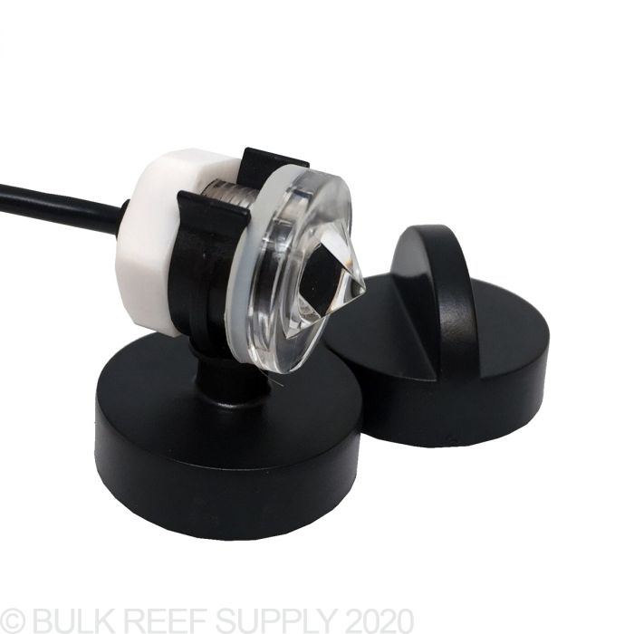
The water sensors are the heart of the system. Solid state optical sensors are used. Float sensors would probably work, but are mechanical and will probably have a shorter lifespan. High end reef controller systems such as Neptune use optical sensors that seem to be from the same company.

One side of the sensor consists of a triangle structure. This structure bounces a light source from one side to a detector on the opposite side. When water covers the triangle piece the light does not bounce back to the sensor.
You can see a small purple-ish component (looks black in the photo below) which is probably the infrared photodiode, AKA the light detector. On the opposing side an led is visible which is likely the infrared light emitter.
The other side is rounded and you can see a chip inside. It is probably a comparator which drives the output signal.


The sensor works off of the fact that without water present the light will bounce back to the detector. However, when water is introduced the light continues into the water and does not bounce back to the detector.
Due to the fact that this sensor uses light, you must consider the positioning of outside light sources. The sensor should be pointing with the triangle structure pointing down towards the water. Aquarium lights are known to be extremely bright so pointing the sensor upwards would probably result in constant "no water" detection. Some reviews on amazon stated that reflective sources interfere with correct operation.

Because the potting material is unknown it should be assumed that it has questionable water proofing abilities.

The "upstairs" portion near the aquarium comes into this box to connect to the relay. The remaining ethernet conductors pass through to the aquarium sensors.
Cable glands are used to pass the ethernet into the box while holding them in place.

The aquarium sensors are mounted to a piece of acrylic. I should have left more slack for future adjustment of the water level sensors.
I considered using a router to make a slot for the sensors so they can be adjusted up and down. That may be a future upgrade.

Most commercial ATO/Auto Top Off systems attach the optical sensors to magnets that go outside the aquarium and hold them in place on the tank. That seems like the easiest approach for easy adjustment.
While the magnetic mounting is convenient and allows easy adjustment I prefer a permanent mounting solution that is more fool proof in the long run.
The neptune system uses headphone jacks which is nice for modularity.
$25 https://www.bulkreefsupply.com/os-1-optical-level-sensor-neptune-systems.html
$35 https://www.bulkreefsupply.com/os-1m-optical-level-sensor-with-mount-neptune-systems.html

The neptune sensors look strikingly similar to these sensors on ebay for ~$3 each sans the headphone jack.

A similar but longer sensor bar is used in the RODI water storage. The sheet of acrylic wasn't long enough to reach the lower water level sensor so I bolted 2 pieces together with stainless hardware.


The temperature probes and sensors are connected via ethernet ports to make everything nice and modular for easy break down.
The Ethernet ports both have many of the pins matching so if you swap the ports on accident nothing will blow up. They are crimped using the "B" standard.
|
| ||||||||||||||||||||||||||||||||||||||||
A micro USB port breakout board delivers power to the arduino and raspberry pi directly to the 5v rails.

The arduino is mounted sideways in a removable socket. I can easily pull it out for reprogram it by removing the few dupont wires.
I prefer the Arduino Pro Micro because it uses the Atmega ATmega32U4. This chip has 2 separate serial ports. So you can have one connected to your application (nodejs running on raspberry pi in my case) and the other connected to your arduino serial terminal for easy debugging.
The only component on the board is a 4k7 pull up resistor for the 1 wire DS18B20 temp probe.

The drain valve is a 24v solenoid valve. This takes significant power to hold open and gets extremely hot to the touch. We can decrease power usage with PWM.
The "drain open" command opens the drain with a 100% PWM duty cycle signal for 1 second then reduces the PWM duty cycle to 50% which is just enough to hold the valve open. The valve stayed open dry at 30% but would not hold the valve open with water flowing through.
This cuts the power usage in half and the valve no longer gets hot.
When the valve closes the power increases again to 100% duty cycle for 1 second to "slam" the valve shut.
A digital pin was left active in case there is a problem with the PWM. The jumper can be swapped so the arduino doesn't need to be reprogrammed.

raspberry pi and arduino connections.pdf
I'm using a 32 gallon garbage can to store the RODI water.

The RODI Storage is auto filled with a float valve. I installed an overflow drain above the float valve for when the float valve eventually fails.
The RO System I'm using has an auto shut off solenoid inside that turns off the water when the float valve fills the barrel. This prevents wasting water. If you use an RO system from Bulk Reef Supply you need to be sure you have an auto shut off valve to prevent wasting massive amounts of water.

The overflow drain is mounted above the float valve.


Water in the RODI storage is heated and aerated with a small 100W submersible heater and a large air stone (so it will sink).

A Jebao DCP-8000 pump is used to refill the tank. This large pump was necessary because of the fact that water is being pumped from the basement up to the main floor. At least 12 feet / 4 meters of head pressure was required.

The drain hose is 1/2" ID Black Vinyl tubing with a stainless mesh filter guard.

For the fill hose, 1" vinyl braided PVC hose model 98579 was used.
In hindsight I should have ordered some "low pressure" tube online. That would have been 1/3 the cost.

For filling the tank this PVC jobber hangs off the back of the tank connecting to the vinyl tube above with a hose clamp on the barb.


The fill tube doesn't touch the water. This avoids creating a siphon when the fill pump turns off, and avoids draining the aquarium into my basement. Seems like a good idea right?

A sheet of acrylic was cut down to 2" strips using a circular saw. Then I torched the edges to smooth them out.
The 2" strip was heated with a heat gun and bent over a piece of wood measuring the thickness of the aquarium.

I drained the aquarium into the RODI storage to find the "tank low" point. The "tank high" is about an inch from the very top of the tank. These points were marked with tape for drilling the water sensor mounting holes.
The water level sensors were fed through some heat shrink tube for additional protection.

I cracked the piece of acrylic when drilling the top hole. I used a torch to melt them and stick them back together. The problem was I used a drill bit rather than a step bit. Drilling large holes into thick acrylic using a step bit should avoid cracking.

Additionally I slathered some hot glue over the exposed portion of the wiring and potting material on the back of the water sensors. I don't believe they were made to be mounted fully submerged. The jacket on the wire did not look very water proofy.

As I put the piece of acrylic into the aquarium- the bent over portion was just a bit too small. When trying to force it over the aquarium edge, the acrylic flexed and snapped back into 2 pieces along the shoddily repaired crack. No surprise there- I didn't expect it to last.
Fortunately I had one spare strip of 2" acryling already cut. I bent and re-drill it and was back in business. Using the step bit this second time around avoided the cracking issue altogether.
The cheap DS18B20 sensors all claim to be waterproof. Double check your sensors before long term submersion! Some of them have no epoxy filling at all.
Edward Mallon of the Cave Pearl Project really stretches the limits of the DS18B20's water proofing capabilities. While his ultimate solution was to fully embed the sensors in epoxy - I figured some improved head shrink would suffice.
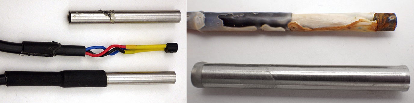
I peeled the heat shrink back on my sensors and found that there was in fact epoxy protecting the DS18B20 within the metal casing. This made me feel better, but as an added precaution I replaced the heat shrink with a heat shrink containing adhesive to further water proof the sensors.

On top is the new heat shrink with embededded adhesive and below is the stock heat shrink

The RODI Low water level sensor needed to be extended so an ethernet cable was soldered on and the whole length was (painfully) pulled through heat shrink cable.

Ethernet cables and jacks (8p8c) were used to connect all the sensors to the arduino board.
The sensor wires were attached together with zip ties and then zip tied to the ethernet cable. Then the wires were soldered and sealed with heat shrink tube.


Single 5v Relay Module Wired Normally Closed for turning OFF the tank filter and circulation pumps during the water change
Relay #1 Wired Normally Open for turning ON the Water Heater and Air Pump and Air Stone for Aeration
Relay #2 Wired Normally Open for turning ON the Tank Fill Pump
Mosfet Module Isolated IRF540 to drive solenoid drain valve
24v DC solenoid valve (normally closed) 1/2" Barb Fittings for draining the tank with a permanent siphon
Doorbell wire for solenoid valve
C14 120v male power cord socket (salvaged out of dead power supply)
Hammond clear project boxes
#1 1591STCL Translucent Polycarbonate Project Box (4.3" x 1.6" x 3.3")
#2 1591DTCL Translucent Polycarbonate Project Box (5.9" x 1.8" x 3.2")
Everything is connected together using Network / Ethernet cable
5v DC power supply (included with pi zero w kit)
USB Micro Break Out board for a nice looking power connection through the box
4.7K 1/8W Resistor for temp probes
1/2" ID x 5/8" OD x 50 ft Flexible Non-Toxic, BPA Free, Black Vinyl Tubing for drain tube. I used black vinyl hoping to slow the growth of algae.
Stainless Mesh Fitler Guard for siphon drain
DS18B20 1-wire temperature probes - 1 for tank and 1 for RODI water storage
Water Sensor, solid state, optical - 2 for Tank High & Low, 2 for RODI Storage High & Low
Double-Side Prototype PCB Universal Printed Circuit Board 4cmx6cm
RJ45 Ethernet Jacks (Vertical) 8P8C These were a pain to mount - I had to bend the pins to fit into the perf board nicely.
Sheet of 1/4" / 0.22" acrylic for sensor mounting
Neiko 10193A Titanium Step Drill Bit Set, 3-Piece Set for drilling 7/16 holes acrylic. A regular drill bit cracked the acrylic!
Kerick Valve MA252 PVC Mini Float Valve, Tank Mount, Adjustable Arm, 1.5 gpm at 60 psi, 1/4" Tube
3/8" RO Water Tube Fitting,Bulkhead Connector for RODI overflow storage drain
Cable Glands to tighten ethernet cables going into electrical box
3/4" PVC Pipe
3/4" PVC Elbows
1" x 3/4" PVC Reducer Bushing Lasco Model 437131RMC
1" x 1" PVC to barb adapter fitting LASCO Model 474010RMC
Jebao DCP-8000 DC Pump (2,110 Gal/Hr. 18ft Max Head. 65 Watt)
Various Electrical Boxes, Outlets, 14awg solid copper wire purchased from home improvement store
2020-09-22 Published
2020-10-03 Add Component List
2020-10-11 Add Water Sensor Photos and Diagram
